Physics Current Electricity Level: High School
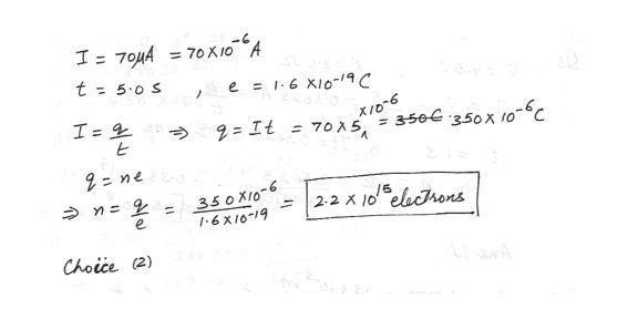
The current in an electron beam ina cathode –ray tube is measured to be 70 A . How many electrons hit the screen in 5.0 s ? (e=1.6 x 10⁻¹⁹ c)a 2.2 x 10¹¹ electrons
b . 8.8 x 10¹³ electrons
c. 2.2 x 10¹⁵ electrons
d. 8.8 x 10¹⁸ electrons
Physics Current Electricity Level: High School
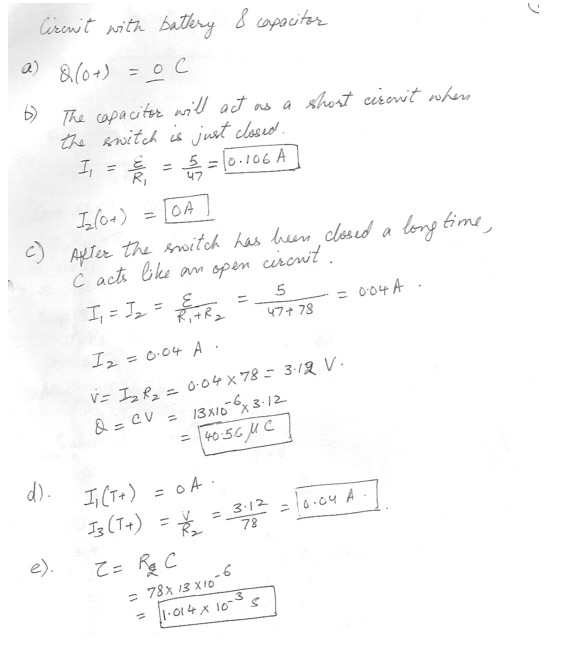
Initially the capacitor is uncharged , and the switch is open . At t = 0, the switch is closed . The positive direction of the currents are represented by arrows in the diagram which is shown at “click here”a) Calculate the charge on the positive plate of the capacitor jus tafter the switch is closed.
b) Calculate the following currents immediately after the switch is closed.
. I1(0+) = A
. I2(0+) = A
c) After the switch has been closed for a long time , calculate the following quantities :
. I1= A
. I2= A
. Q= C
d) At some yet later time T, the switch is again opened . Calculate the following currents immediately afterward .
I1(T+) = A
I3(T+) = A
e) What is the time constant of the discharging circuit ?
Physics Current Electricity Level: High School
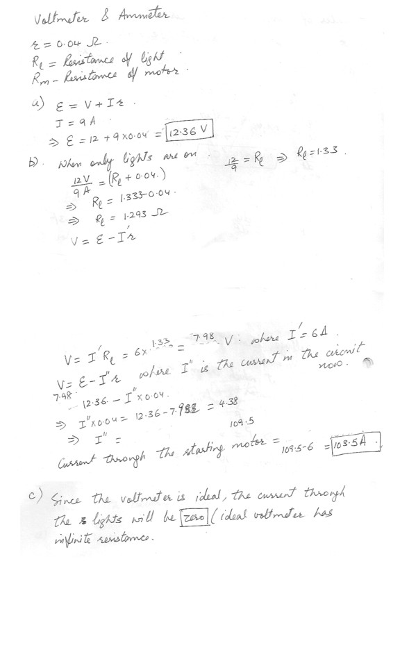
When the lights on an automobile are switched on , an ammeter in series with them read 9A and a voltmeter connected across them read 12 V . When the electric starting motor is turned on, the ammeter reading drops to 6A and the light dims somewhat . You may assume that the ammeter and the voltmeter are ideal , The internal resistance of the battery is 0.04ohm .a). What is the EMF of the battery ?
b). What is the current running through the starting motor when the lights are on?
c). Now positions of the voltmeter and the ammeter is interchanged in the circuit as shown in the figure at “click here “ . The switches are set so that the lights can turn on but the starting motor will not. what is the current flowing through the lights ?
Physics Current Electricity Level: High School
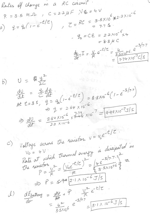
A 3.5 M ohm and a 2.2 micro F capacitor are connected in series with an ideal battery with an EMF of 4 V. At 3 seconds after the circuit is initially connected to the battery :a. What is the rate at which the charge on the capacitor increasing ?
b. What is the rate at which energy is being stored on the capacitor ?
c. What is the rate at which thermal energy is appearing in the capacitor ?
d. What is the rate at which energy is being delivered by the battery ?
Physics Current Electricity Level: High School
In the circuit as shown in the figure at “click here” has. E = 2V
. r=80 ohm
. R1 = 280 ohm
. R2 = 360ohm
. Internal resistance of the voltmeter = 6 x 10^3 ohm
. The ammeter is ideal (ie, its internal resistance is zero )
(a) What is the magnitude of the percentage error the voltmeter introduces when trying measure the potential difference across R1 ?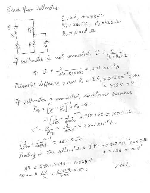
Physics Current Electricity Level: High School
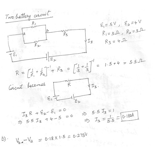
The circuit in the figure which is shown at ‘click here” is composed of two batteries ( E1=5V and E2=4V ) and three resistors (R1 = 3ohm, R2 = 3ohm, R3=4ohm) as shown.a . What is the current I 3 flowing through the batteries ?
b . What is the voltage Vb-Va between the points a and b in the circuit ?
Physics Current Electricity Level: High School
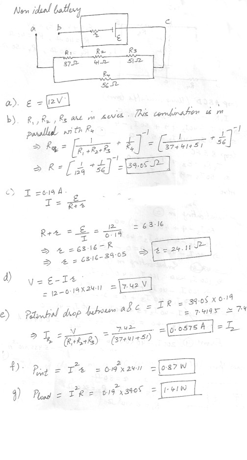
The point b and c on the diagram at “click here” are the terminals of a battery with EMF E and internal resistance r. the circuit resistors have the following values : R1 = 37 ohm, R2 = 41 ohm, R3 = 51 ohm, R4 = 56 ohma. An ideal voltmeter is connected between b and c; it reads Vc-Vb = 12V. What is the EMF of the battery ?
b. What resistance would an ohmmeter connected across points a and c read ?
c. An ideal ammeter is inserted between points a and b it reads 0.19A. Determine the internal resistance of the battery ?
d. What does the voltmeter connected across b and c read now ?
e. Calculate the magnitude of the current through R2 .
f. At what rate is thermal energy (heat) being produced inside the battery ?
g. What is the power being provided by the battery to the external circuit (outside the battery)
Physics Current Electricity Level: High School
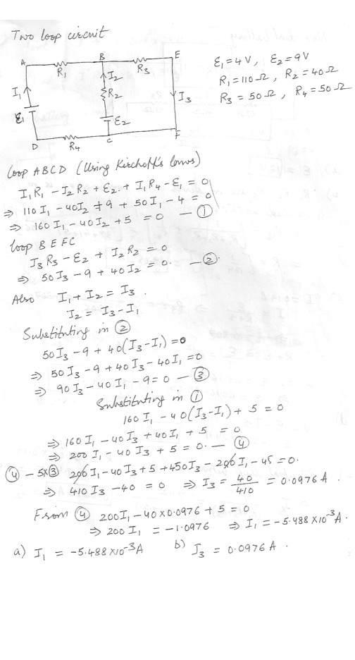
The circuit in the figure which is shown at “click here” is composed of two batteries (V1=4V and V2 = 9V) and four resistors (R1 = 110 ohm, R2 = 40 ohm, R3 = 50 ohm, and R4 = 50 ohm ) as shown .(a) What is the current which flows through R1 ?
(b) What is the current I 3 that flows through R3 ?
Physics Current Electricity Level: High School
Determine the power dissipated by each resistor in the attached circuit .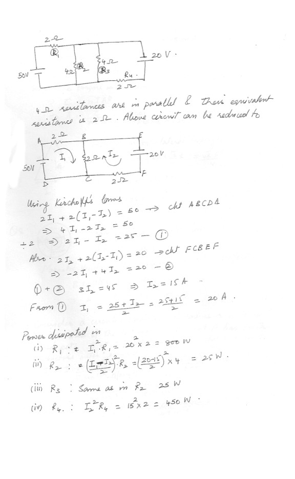
Physics Current Electricity Level: High School
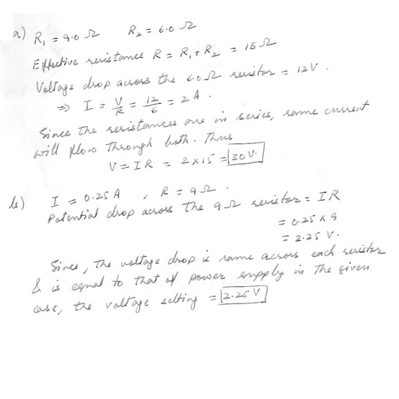
A 9.0 ohms resistor and 6.0 ohms resistor are connected in a series with a power supply .(a) The voltage drop across the 6.0 ohms resistor is measured to be 12V . Find the voltage output of the power supply
(b) The two resistor are connected in parallel across a power supply , and the current through the 9 ohms resistor is found to be .25A . Find the voltage setting of the power supply
Physics Current Electricity Level: High School
Find the current through each resistor in the diagram as shown at "click here" .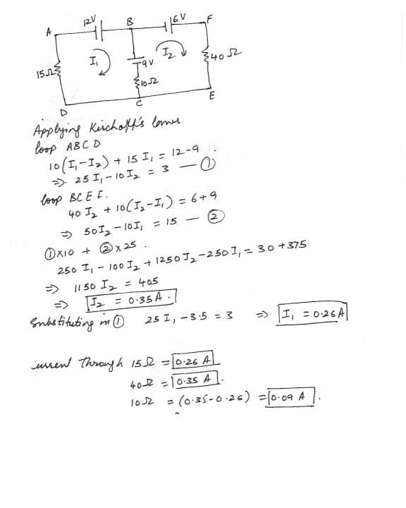
Physics Current Electricity Level: High School
An extension cord made of two wires of diameter 0.129 cm and of length 2.7m(9.0 ft) is connected to an electric heater which draws 10.0 A on a 1.2 x 10^2 V line. How much power is dissipated in the cord?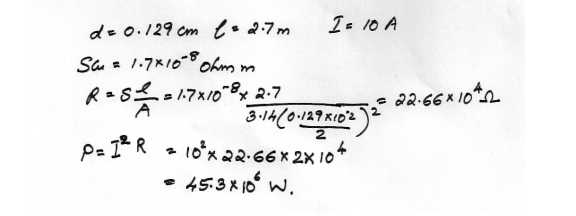
Physics Current Electricity Level: High School
At $ 0.071 per kWh , what does it cost to leave a 1.0 x 10^2- W porch light on day and night for a year ?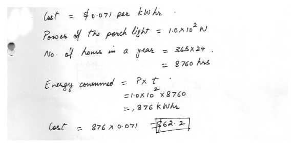
Physics Current Electricity Level: High School
What is the maximum voltage that can be applied across a 7.3 k ? resistor rated at 1/4 watt ?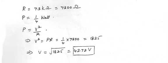
Physics Current Electricity Level: High School
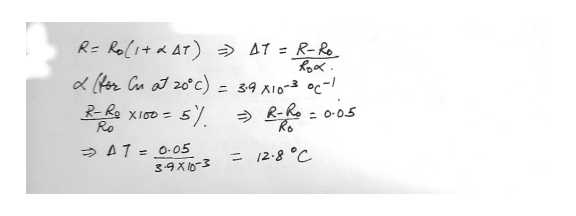
How much would you have to raise the temperature of a copper wire (originally at 20.0 degree C) to increase its resistance by 5.00 percent ?